

HV-Pulse Generators
Magnet Pulse Generator
Magnet Pulse Generator
Custom tailored for medical applications
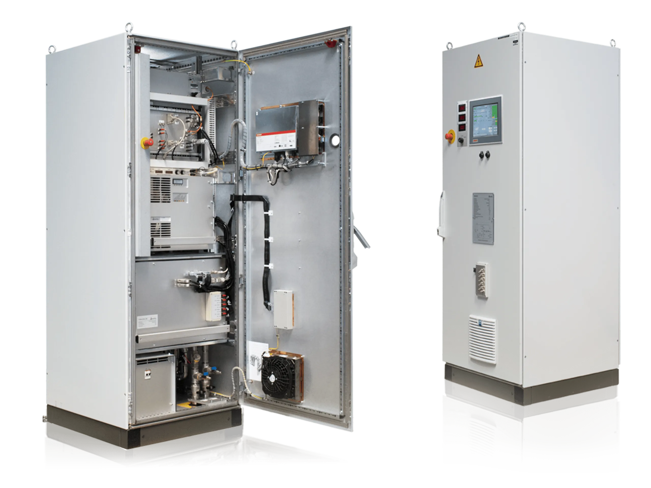
Poynting GmbH has built and delivered a custom specific designed pulse generator for MedAustron, a centre for ion therapy and research in Austria, close to Vienna.
The delivered pulse generator SVM-630A controls four kicker magnets which are used to either lead the particle beam from synchrotron ring to irradiation rooms or into a dumping block. In this way the beam chopper is used to switch the beam in the irradiation room on and off, thus the switching function of the pulse generator is used to dose the beam as the medical front end demands.
The second main function of the pulse generator is to ensure that the current will be switched off within a specified time limit (here ≤ 250 μs) by all means, in particular at failure situations or emergency stop during beam operation.
Mains frequency
50
Hz
Repetition rate
up to
2
kHz
Technical data
| Nominal input voltage 400 | 400 VAC |
| Mains frequency | 50 Hz |
| Maximum input current | 50 A |
| Type of output current | pulsed, DC |
| Maximum repetition rate (normal operation) | 20 Hz |
| Maximum repetition rate (burst) | 2 kHz |
| Maximum output current | 630 A |
| Maximum output terminal voltage | 1500 V |
| Maximum average output voltage | 70 V |
| Typical inductance | 345μH (+-20%) |
| Typical resistance | 32mΩ (+-30%) |
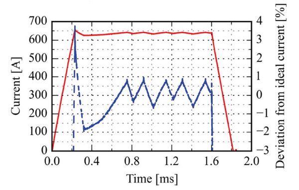
Measured current pulse (solid red: magnetcurrent, dashed blue: deviation from ideal current) [wepma002.pdf], validation of pulse specifications.
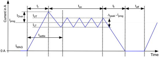
Waveform
| Pulse frequency | fmax | DC to 20 Hz | |
| Current amplitude range | Iprog | 100 A – 630 A | |
| Current setting resolution | Ires | 1 A | |
| Current ramp shape | linear | non-linearity dependent load inductance and resistance | |
| Ripple | Δpeak | ≤2.5% | peak to peak current ripple on flat top |
| Settling time | tsettle | 400 μs | from trigger to stable operation within |
| Maximum current rise time | trise | <250 μs | typical load, 630 A, 95%, incl. trigger delay |
| Maximum current fall time | tfall | <250 μs | typical load, 630 A, 10%, incl. trigger delay |
| Maximum current overshoot | Iover | 5% of set value | typical load |
Emergency shutdown at failure
| Δpeak | Peak to peak current ripple on flat top of output current > 3 % |
| tsettle | Current overshoot of output current > 5 % |
| trise | Time from reception of start trigger until at least 95 % of output current > 250 μs |
| tfall | Time from reception of stop trigger until at most 10 % of output current > 250 μs |
You may also be interested in
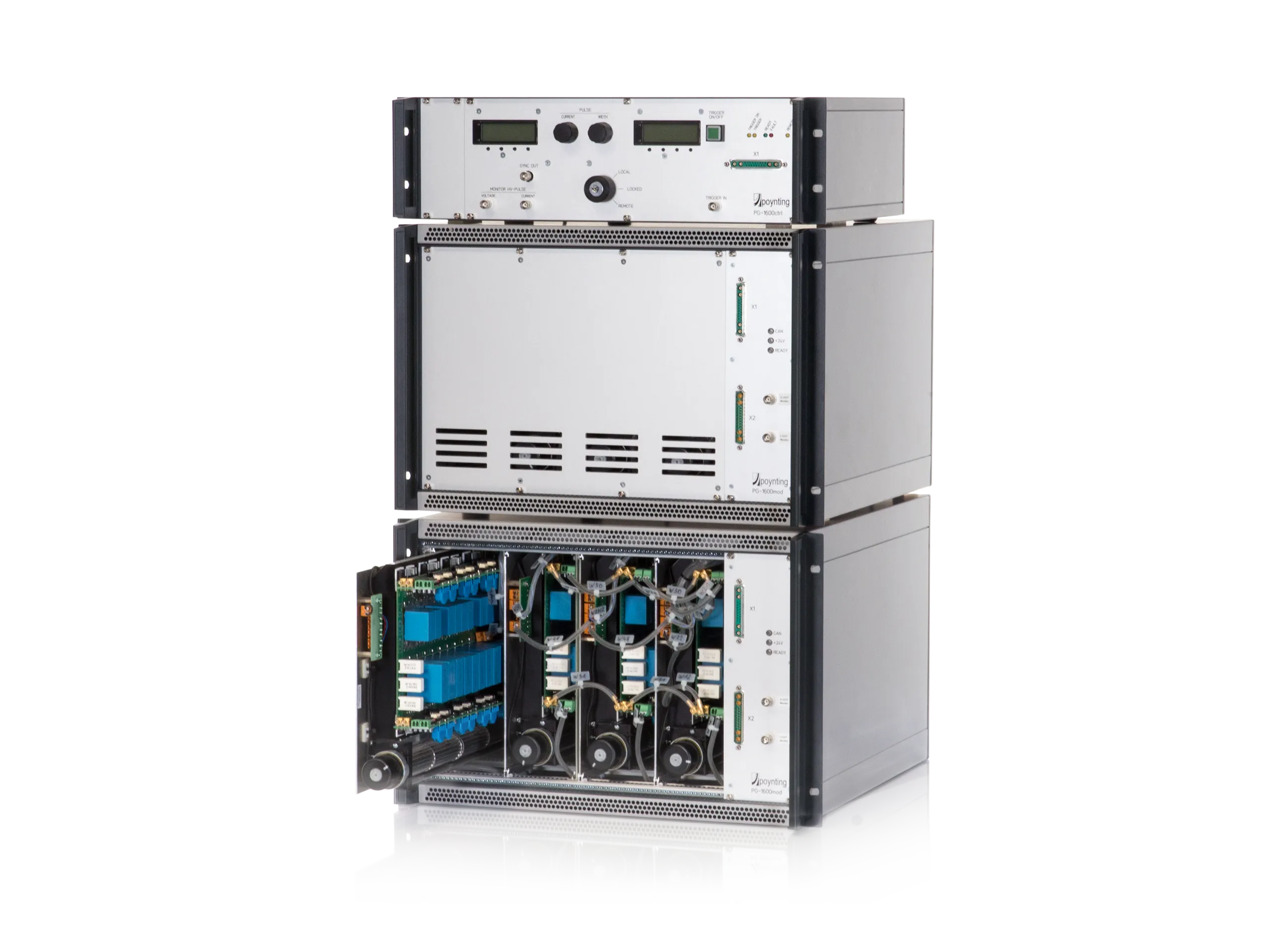
PG modular system
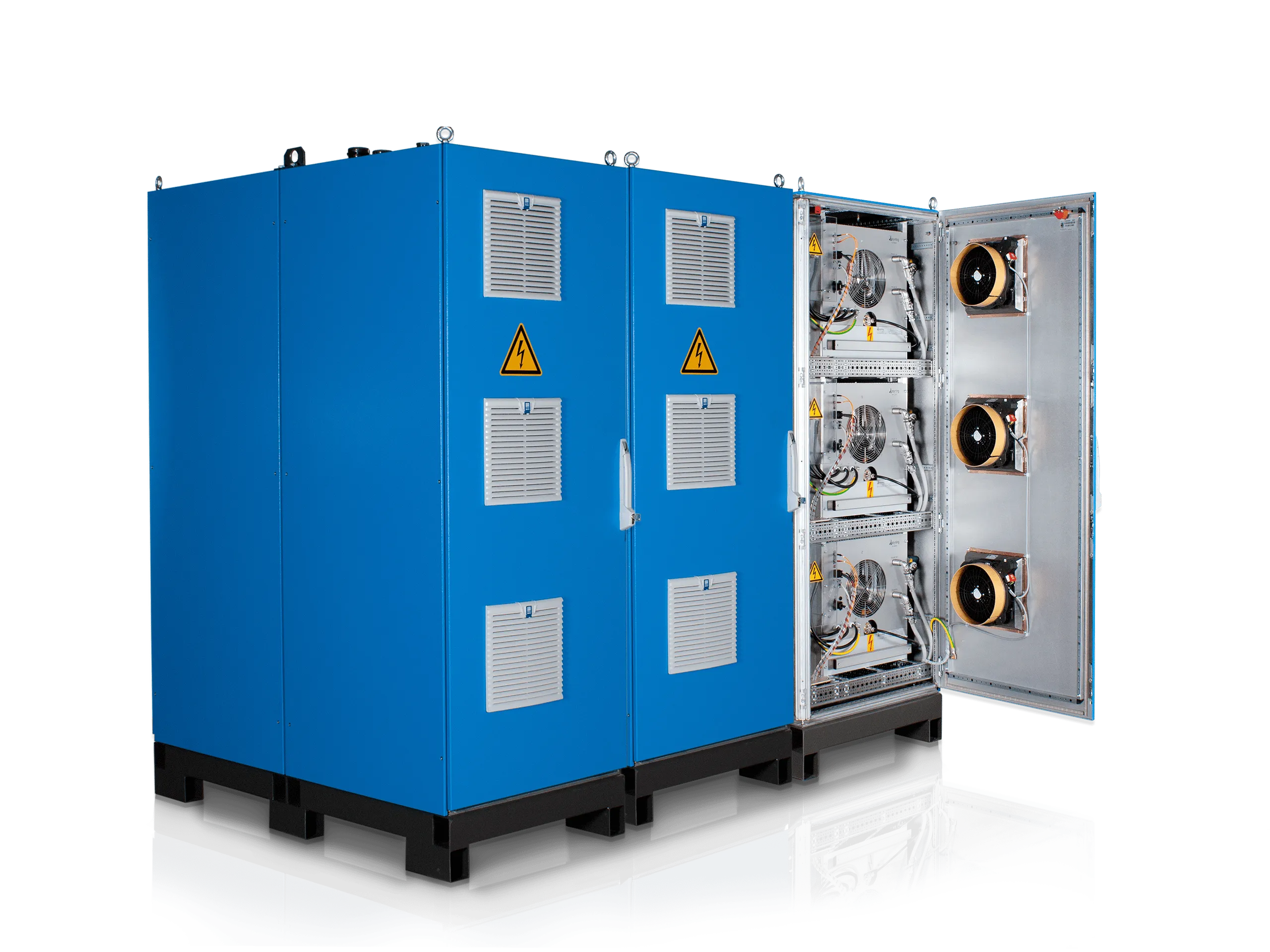
Power supplies
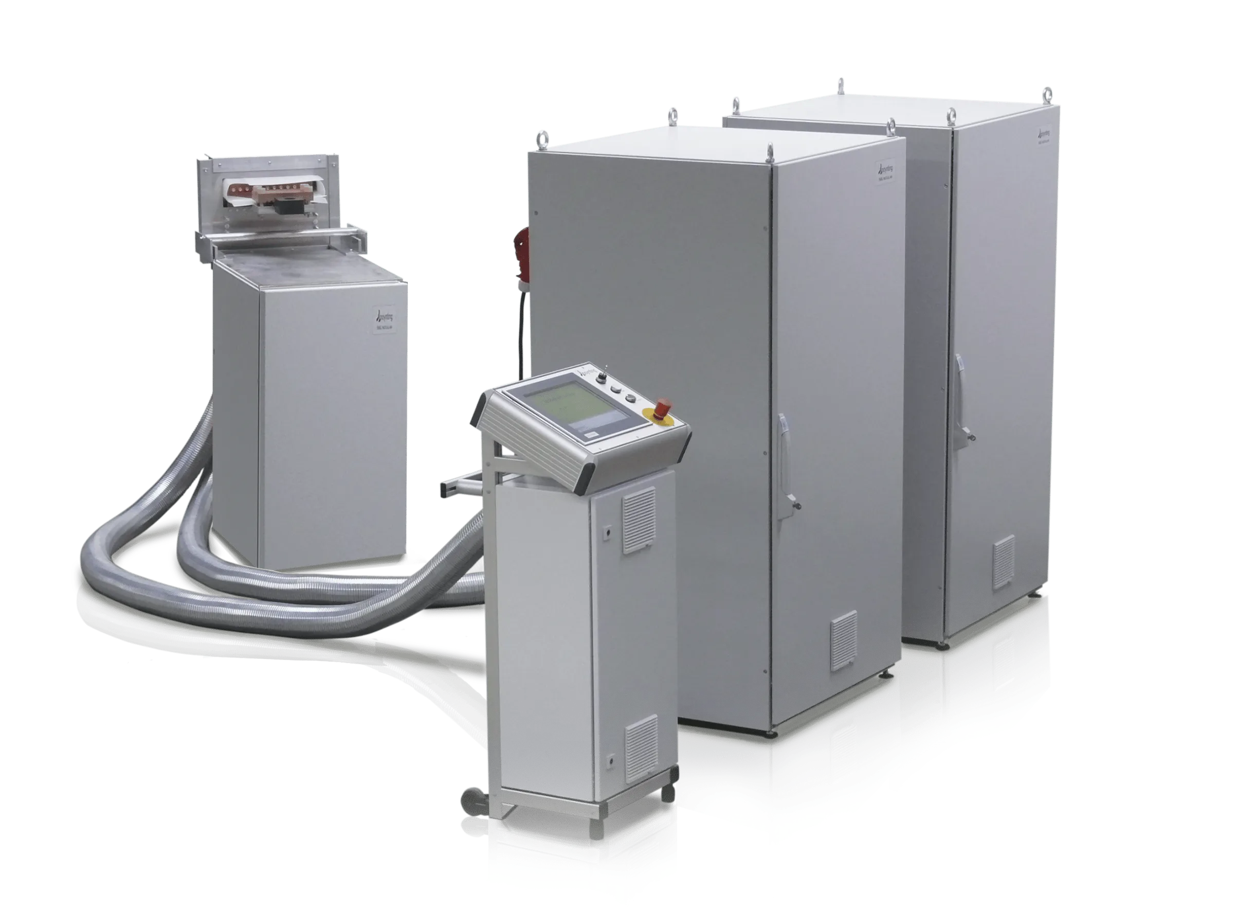
EMF Systems